When we start to DC fan project, there is this small component called MOSET transistor is used to act as a switch for Arduino to control via PIN signal. What is MOSET transistor?
- MOSFET stands for Metal Oxide Field Effect Transistor, MOSFET is a voltage-controlled device, meaning by applying a rated voltage to the gate pin, the MOSFET will start conducting through the Drain and Source pin.
- Let look at the brief history of MOSFET.
- The basic principle of the field-effect transistor (FET) was first proposed by Austrian physicist Julius Edgar Lilienfeld in 1926.
- Semiconductor companies initially focused on bipolar junction transistors (BJTs) in the early years of the semiconductor industry. However, the junction transistor was a relatively bulky device that was difficult to manufacture on a mass-production basis.
- In November 1959, Mohamed Atalla and Dawon Kahng successfully fabricated the first working MOSFET device.

Symbol Of MOSFET
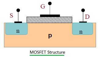
- In general, the MOSFET is a four-terminal device with a Drain (D), Source (S), gate (G) and a Body (B) / Substrate terminals. The body terminal will always be connected to the source terminal hence, the MOSFET will operate as a three-terminal device.
- MOSFETs are available in two basic forms:
- Depletion Type: The transistor requires the Gate-Source voltage (VGS) to switch the device “OFF”. The depletion-mode MOSFET is equivalent to a “Normally Closed” switch.
- Enhancement Type: The transistor requires a Gate-Source voltage(VGS) to switch the device “ON”. The enhancement-mode MOSFET is equivalent to a “Normally Open” switch.
- Similar to above Depletion and Enhancement Type, main difference between the N-Channel MOSFET and P-Channel MOSFET is that in an N-channel, the MOSFET switch will remain open until a gate voltage is provided. When the gate pin receives the voltage, the switch (between Drain and Source) will get closed and in P-Channel MOSFET the switch will remain closed until a gate voltage provided.

Working Principle of MOSFET
- In general, the MOSFET works as a switch, the MOSFET controls the voltage and current flow between the source and drain.
- The typical current versus voltage (I-V) characteristics of a MOSFET are shown in the figure below.
- The cutoff region is the region where the MOSFET will be in the OFF state where the applied bias voltage is zero. When the bias voltage is applied, the MOSFET slowly moves towards conduction mode, and the slow increase in conductivity takes place in the ohmic region. Finally, the saturation region is where the positive voltage is applied constantly and the MOSFET will be staying in the conduction state.

Thanks for reading and hope you stay safe.
